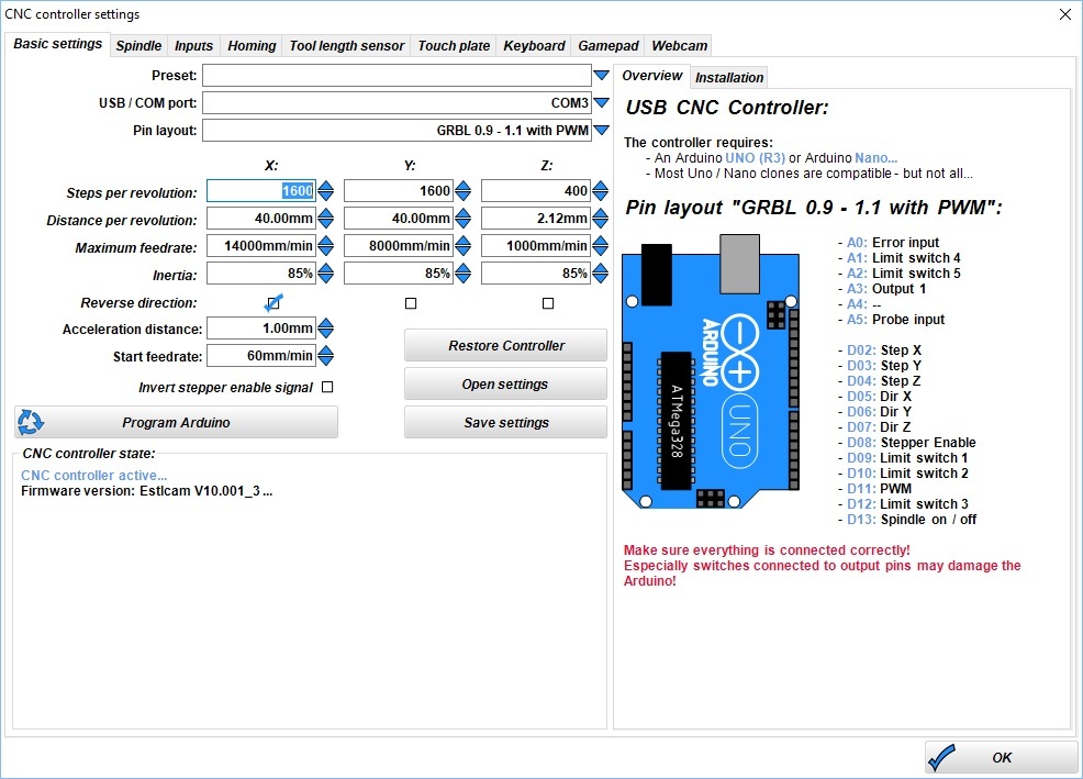
Now that the physical components are set, the working area of the milling machine needs to be set up. Also the hose of the vacuum cleaner should be fixed to it. Afterwards adjust and fix(!) the drilling machine with the Allen screw ("Imbus" Schraube in German) seen in the picture below. The outer contour should be 4mm so that it will drill through the first material.īefore the actual milling process can be initiated, make sure that the right drill head is put and fixed inside the drilling machine. If the working piece material is 3mm thick, a depth of 1mm should be enough for the actual engraving. In Parameters > Tools > Measure the plunge depth (in mm) can be set for every outline. When the size is as planned, the parameters for the materials have to be set. After changing those, you will see the results in the coordinate system and can check if it will have the planned size regarding the working piece material which will be milled. There you can set up the scaling factor for every axis. For example, when the measurements for the actual working piece material differ from the sketch file, this can be set up in the tab Coordinates. This way one could for example mill only the sketch itself but not the outer outline.Ĭlicking Parameters > Tools will open up the settings, in which some parameters need to be set. By clicking you can hide/unhide them which sets up if those will be considered or not for the milling process. For example in the figure below you can see that 1 and 6 are outlines. The third toolbar shows all the single outlines indicated by color and numbers.

This means that the final result will actually be turned 90° counter-clockwise. In the picture below you can see what the result of this sketch looks like. However, the orientation is not the same as the one you see in the preview. If you want to mill the sketch in different measurements, the different axes can be adjusted as we will explain in the next steps. With this you can check the measurements and dimensions of your sketch. , which will show up a preview in a coordinate system. Now you can load up your sketch you want to mill via If the name of the milling machine is shown in orange letters like in the picture below, everything is correct. If you now open up WinPC-NC, a second small window should open up, which shows if the machine was connected properly: As of right now, there is no practical solution to this issue aside from opening the doors and trying to look around to see the LEDs.
ESTLCAM SVG MANUAL
If it does not, please refer to the manual as it helps with troubleshooting.Įdit: Inside of the enclosure, the LEDs are not easily visible at the back of the enclosure. It should look like this in order to function properly: On the left side of the machine you can find LEDs which indicate the status. For this it should be connected to a power socket and also to the USB port of the MacBook. Yes, fixating and moving the downholders can be very hard.Īfter this the milling machine can be turned on. Additionally screws should be tightened into some of the holes of the downholders in order to fixate the material even more (this can be done by hand or via an electric screwdriver). The metal "downholders" then need to be fixated into the slots on the sides of the milling machine so that they keep both materials down.

ESTLCAM SVG SOFTWARE
The native software for the milling machine is WinPC-NC, which is installed on the MacBook via Parallels.Īt first both materials are placed onto the working surface, whereas the sacrificial plate is to be put down first and on top of it the actual working piece material. In general there are 2 materials required to mill, which are put onto the working surface.


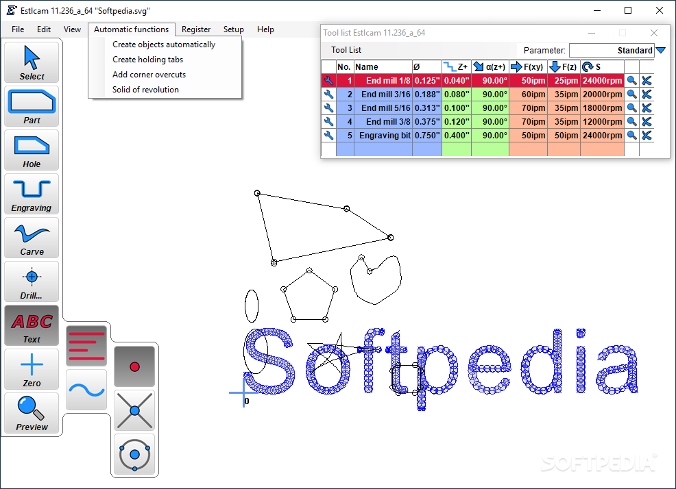
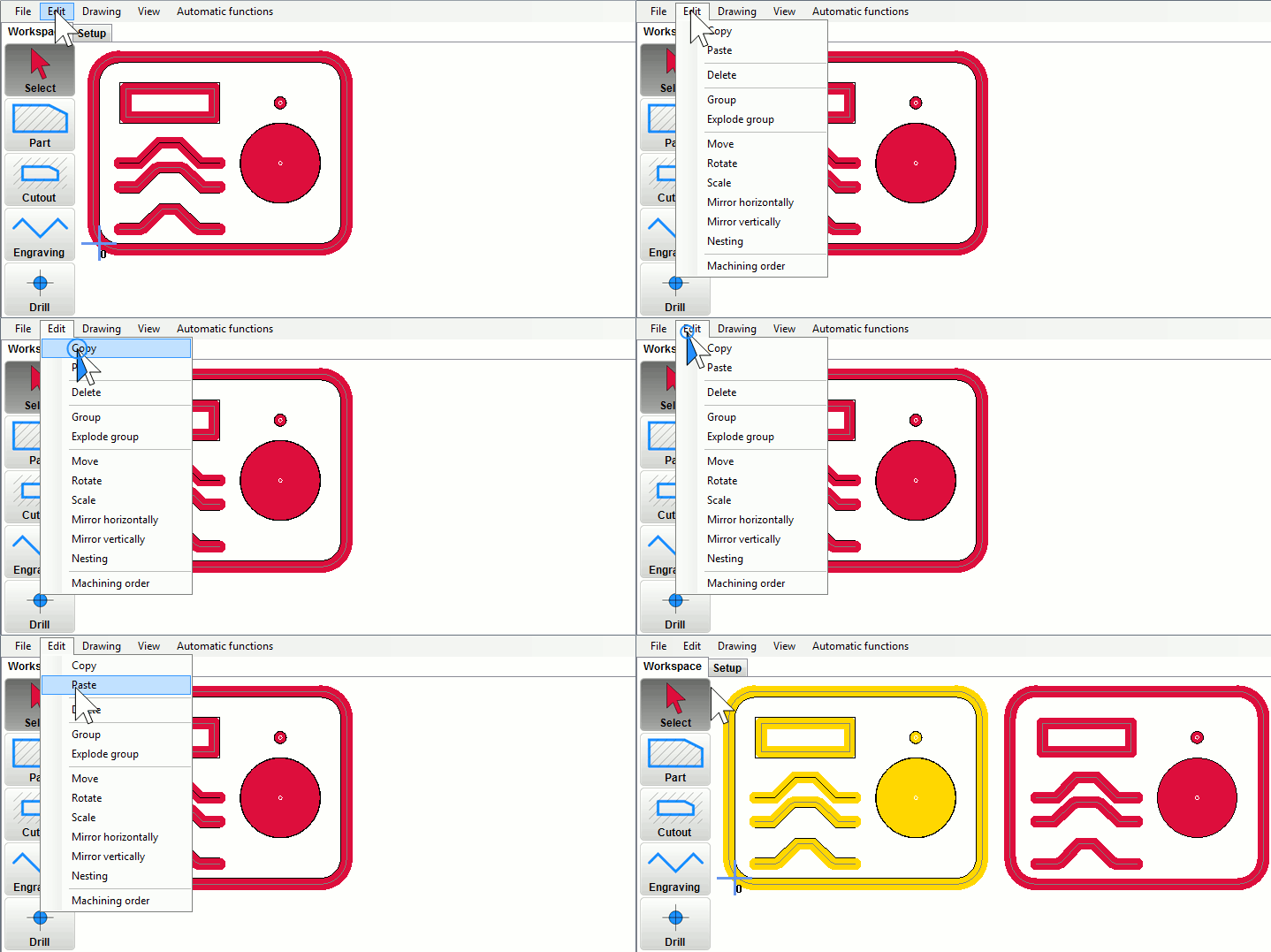
Inkscape is suited very well to draw 2D engravings, which can then be exported as. svg files need to be converted into one of these formats first. In terms of 2D milling WinPC-NC accepts the following file formats. Because of lots of different factors which can be considered and some of them need to be considered, we will discuss those in particular. The Stepcraft is suited for milling of 2D and 3D models with materials such as wood or aluminium. The current and updated documentation for the Stepcraft using Fusion 360 and UCCNC can be found here.


 0 kommentar(er)
